P & ID common symbols, How to read a P&ID. 계장설비2020. 9. 11. 08:06
Piping and Instrumentation Diagrams (P&ID) are schemes of pipelines, equipment, instrumentation, control systems, from a process system found in Oil Refinery, Chemical Plant, Paper Mill, Cement Plant, etc.
The symbols contained in P & ID represent equipment such as actuators, sensors and controllers. Process tools such as valves (valves), instruments, and pipelines are identified by code. The codes are based on the size, type of fluid being drained, type of pipe connection (such as using Bolt or Flang), and the status of the Valve status (Normally Close or Normally Open).
How to read a P&ID?
The Instrumentation codes listed in P & ID are as follows, the first letter identifies the parameters that are controlled, the letters then identify the type of control device

Based on the example of the P & ID diagram above, FT101, the first letter F has the meaning of the code (based on the ISA code), namely Flow.
| First letter | Parameters controlled |
| A | Analysis |
| C | Conductivity |
| D | Density |
| E | Voltage |
| F | Flow Rate |
| I | Current |
| L | Level |
| M | Moisture(Humidity) |
| P | Pressure or Vacuum |
| T | Temperature |
| V | Viscosity |
The second letter T has the meaning Transmitter, code FT101 can be interpreted as Flow Transmitter, Circles indicate FT101 mounted (mounted) in the Field Area, which is connected by electric signal (dashed line).
| Next letter | Control equipment type |
| A | Alarm |
| C | Controller |
| I | Indicator |
| T | Transmitter |
| V | Control Valve |
| E | Element |
| IC | Indicator Controller |
| FC | Ratio Controller |
| R | Recorder |
| HS | Hand Switch |
| HV | Hand Valve |
| Q | Totalizer |
| IQ | Indicating Totalizer |
| XV | Solenoid Valve |
| Y | Calculation |
| FY | Ratio Callculation |
| SL | Switch Low |
| SH | Switch High |
| AL | Alarm Low |
| ALL | Alarm Low Low |
| AH | Alarm High |
| AHH | Alarm High High |
In FIC101, meaning (Flow Indicator Controller), the symbol in the form of a box and circle shows FIC101, located in Shared Control / Shared Displays and can be accessed by the operator.
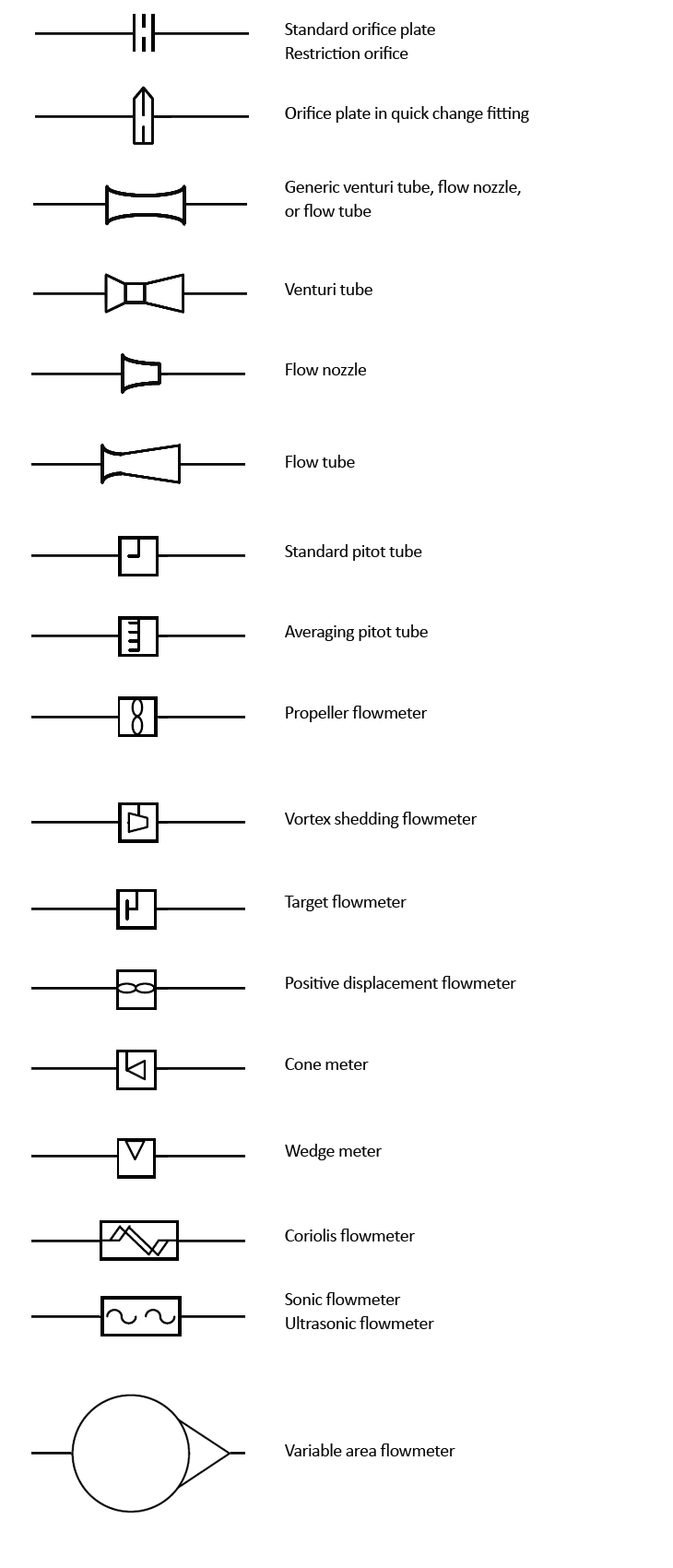
Process and Instrumentation Symbols – Instruments
The process flow diagram uses symbols and circles to represent each instrument and how they are interconnected in the process.

Process and Instrumentation Symbols – Equipments:
Pumps and tanks come in a variety of designs and shapes.


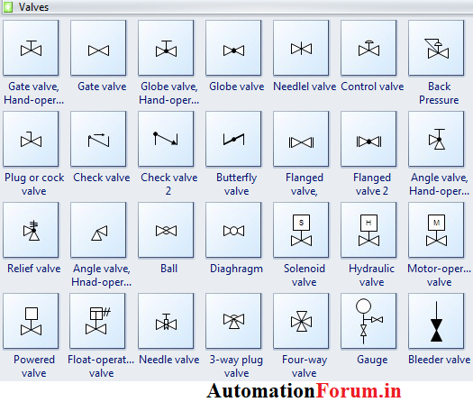
Process and Instrumentation Symbols – Valves:
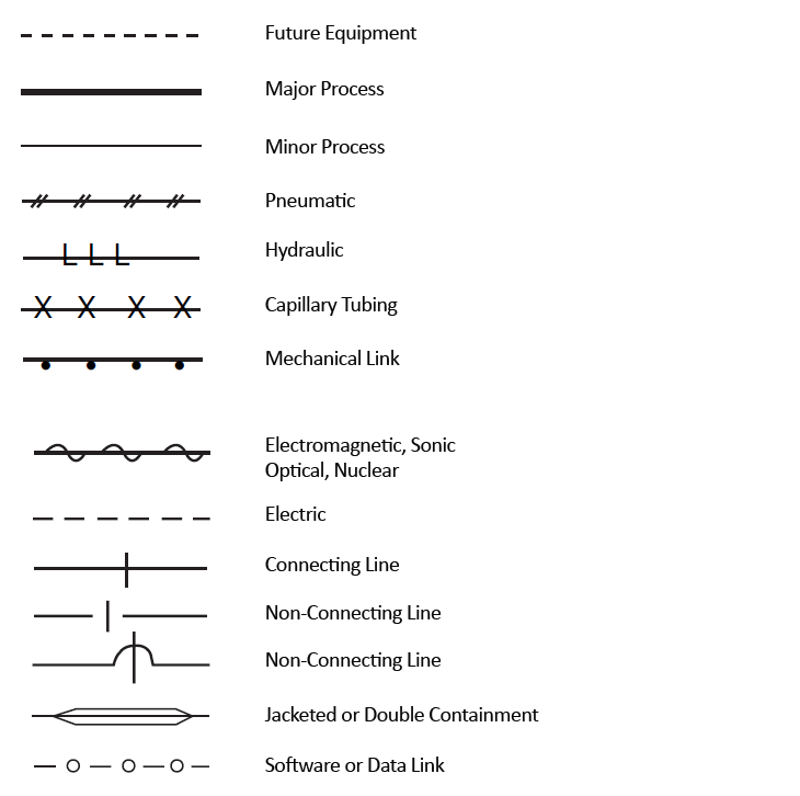
Process and Instrumentation Symbols – Piping Lines:
Process flow diagrams use special pipe lines to represent how signals are transmitted between equipment. These symbols are used to identify how the instruments in the process connect to each other. And what kind of signal is being used. (electrical, pneumatic, data, etc.)

'계장설비' 카테고리의 다른 글
| P&ID legends (0) | 2020.09.11 |
|---|---|
| What is the difference between control panel and MCC? (0) | 2020.09.11 |
| 1. 감압밸브[PRV, PRESSURE REGULATING VALVE] (0) | 2020.08.27 |
| 2. 안전밸브[SAFETY VALVE] (0) | 2020.08.27 |
| 3. Relief Valve 와 Safety Valve 차이점 (0) | 2020.08.26 |