ON-OFF 제어 방식 전자 접촉기의 Open-Close 방식처럼 On 신호시 출력 100%, Off 신호시 출력이 0%로 완전히 차단되는 방식이나 반도체 소자의 Switching이므로 무접점제어로 소음과 진동이 없고 Arc가 발생되지 않습니다. 정전압 제어 방식 일반적으로 가변저항기(VR)로서 제어값을 설정하여 부하에 항상 일정한 출력을 공급하는 방식으로 전기로 또는 전열 블럭의 Base Heating등에 사용하는 방법이며, Control Heating과 병행하는 경우가 흔합니다.
연속 제어 방식 가장 많이 사용하는 제어방식으로 온도조절계등의 전용 Controller로부터 4-20mA의 제어 신호를 받아 전력을 제어하는 방식입니다. P.I.D 방식의 Controller와 조합하여 정밀한 온도제어를 구현합니다.
정전력 제어 방식 규화몰리브덴 발열체, 탄화규소 발열체, 백금합금 발열체등과 같이 저항 온도계수가 온도에 따라 변하는 Heater에 적용하는 제어방식으로 전력 조정기 전단에 전력 변환기를 설치, 변환기 신호에 따라 출력을 조정하는 방식이 일반적입니다
위상제어 AC전원은 50Hz 및 60Hz의 주파수를 가지고 있으며 60Hz 1/2싸이클의 시간은 약 8.33ms이며 위상각은 0~180°의 수치를 나타내고 있습니다. 위상제어 방식은 AC의 전압의 1/2 싸이클을 입력제어 신호에 따라 8.33ms동안 0~180°를 비례적으로 아래 그림과 같이 분할 제어하여 출력시키는 방식입니다. 위상제어 방식은 AC파형에 따라 아주 미세하게 제어하므로 AC 전압을 직접 제어할 수 있어 AC 모터, 히터 및 밸브 등 각종 저기 제어기기를 손쉽게 제어할 수 있습니다.
싸이클제어(제로크로싱 방식) 싸이클제어 방식이란 부하전원을 일정한 임의주기 동안에 입력제어 신호에 따라 일정한 비율로 아래 그림과 같은 ON/OFF 주기를 반복하여 부하에 인가되는 전력을 제어하는 방식입니다. 싸이클 제어방식은 부하전원을 ON/OFF할 때 AC의 ZERO점에서 항상 ON, 또는 OFF하므로 위상제어 방식에 비하여 NOISE가 발생하지 않으며 부하제어 직선성이 양호합니다. 그러나 유도성 부하에는 사용할 수 없는 것이 단점입니다.
Color coding of wires in a cable according to IEC 60757
Color Abbreviation
Color(ENG)
Color(KOR)
Abbreviation
Black
흑색
BK
Brown
갈색
BN
Red
빨강색
RD
Orange
주황색
OG
Yellow
노란색
YE
Green
녹색
GN
Blue
파란색
BU
Violet
보라색
VT
Grey
회색
GY
White
흰색
WH
Pink
분홍색
PK
Gold
금색
GD
Turquoise
청록색
TQ
Silver
은색
SR
Green - Yellow
녹색/노란색
GNYE
Twisted pairs in a cable
The definition is given are according to DIN 47100, although this standard isn't valid since 1998. Most cable manufacturers nevertheless use this standard, because nothing else exists.
Pair No.Wire 1Wire 2
1
white
brown
2
green
yellow
3
grey
pink
4
blue
red
5
black
violet
6
grey/pink
red/blue
7
white/green
brown/green
8
white/yellow
yellow/brown
9
white/grey
grey/brown
10
white/pink
pink/brown
11
white/blue
brown/blue
12
white/red
brown/red
13
white/black
brown/black
14
grey/green
yellow/grey
15
pink/green
yellow/pink
16
green/blue
yellow/blue
17
green/red
yellow/red
18
green/black
yellow/black
19
grey/blue
pink/blue
20
grey/red
pink/red
21
grey/black
pink/black
22
grey/black
red/black
Pair no. 23 starts with coding from pair no. 1 again.
제14조(전기장치 일반사항) ① 공작기계의 일부를 구성하는 모든 전기기계기구(이하 "전기장치"라 한다.)는 가능한 공작기계의 전기장 치(KS B 4006) 또는 산업용 기계류의 안전성-기계의 안전장비(KS C IEC 60204-1)를 따라야 한다.
전기장치사양(KS C IEC 60204-1)
9.2.5 운 전 (1) 일반사항 - 적절한 상호 인터록 기능 - 정지된 후 불시기동방지 기능 (2) 기 동 - 안전장치가 정상 설치되고 제 기능유지 시에만 기동 - 기동 제어반이 하나 이상일 경우 다음을 충족 ․ 각 제어반은 별도의 수동식 기동 제어기구가 구비 ․ 모든 기동제어기구는 기동 전 OFF상태 ․ 모든 기동제어기구는 동시에 작동준비 (동기를 맞출 필요는 없다.) - 이동식 기계류는 운전제어를 수동 또는 적절한 방식 (3) 정 지 - 정지방식은 위험분석에 의할 것. - 정지기능은 기동기능보다 우선. - 정지기능 복귀 시 위험(불시기동)을 유발하지 않을 것. (4) 비상정지 - 다른 모든 기능에 우선 - 기계의 전원을 신속히 제거 - 복귀 시 재 기동 되지 않을 것 - 비상정지방식은 배선에 의한 전자기계적 요소로 구성 - EMO(분류0) 또는 EMS(분류1) 중 하나만 허용 - 비상정지 채택 여부는 위험성 평가에 따라 결정 (5) 지시 작동감시 위험 상황을 초래할 수 있는 기계 운전은 감시될 것
10.2 누름버튼 10.2.1 색상 누름 버튼 액추에이터는 표 2에 따라 색상 부호화하여야 한다(9.2 및 부속서 B 참조). 기동/투입 액추에이터의 색상은 흰색을 기본으로 하되, 흰색, 회색 또는 흑색을 사용할 수 있다. 녹색 또한 허용되나 적색을 사 용해서는 안 된다. 적색은 비상 정지 및 비상 전원 차단 액추에이터에만 사용되어야 한다. 정지/차단 액추에이터의 색상은 흑색을 기본으로 하되, 흑색, 회색 또는 흰색을 사용할 수 있으나, 녹색을 사용해서는 안 된다. 적색 또한 허용되나, 비상 조작 장치에 근접한 곳에서 사용해서는 안 된다. 흰색, 회색 또는 흑색은 교대로 기동/투입 및 정지/차단되는 누름 버튼 액추에이터용 색상으로 사용할 수 있으나, 적색, 황색 또는 녹색은 사용해서는 안된다(9. 2. 6 참조). 흰색, 회색 또는 흑색은 누름 버튼을 누르고 있는 동안만 작동하고, 누름을 멈추면 작동을 멈추는 형식의 누름 버튼 스위치에는 사용할 수 있으나 적색, 황색 또는 녹색은 사용해서는 안 된다. 복귀 기능 누름 버튼은 청색, 흰색, 회색 또는 흑색이어야 한다. 이것이 정지/차단 버튼의 역할을 하는 경우, 흑색을 기본으로 하되 흰색, 회색 또는 흑색을 사용할 수 있으나 녹색은 사용하지 않아야 한다. 흰색, 회색 또는 흑색과 동일한 색상이 여러 기능용으로 사용되는 경우(예: 기동/투입 및 정지/차단 액추에이터에 흰색 사용), 부호파의 복수적 수단(예: 모양, 위치, 구조)이 누름 버튼 액추에이터의 식별에 사용되어야 한다.
표 2 – 누름 버튼 액추에이터의 색상 구분 및 의미
색상
의미
설명
적용 예
적색
비상
위험상 상태 또는 비상 시 작동
비상 정지 스위치 비상 기능의 초기화(10.2.1 참조)
황색
비정상
비정상 상태 발생시 작동
비정상 상태를 해소하기 위한 간섭 차단된 자동 주기 재기동 간섭
청색
의무
의무 작동이 필요한 상태의 작동
복귀 기능
녹색
정상
정상 상태의 작동
10. 2. 1 참조
흰색
기동/투입(선호됨), 정지/차단
회색
지정된 의미 없음
비상 정지 이외의 일반적인 기능 개시 (비고 참고)
기동/투입, 정지/차단
흑색
기동/투입, 정지/차단(선호됨)
비고 부호화의 부수적 수단(예: 모양, 위치, 구조)이 누름 버튼 액추에이터의 식별에 사용되는 경우, 흰색, 회색 또는 흑색과 동일한 색상은 여러 기능용으로 사용될 수 있다(기동/투입 및 정지/차단 액추에이터에 흰색 사용)
- 기동(START/ON) ; 녹색, 흰색, 회색 또는 흑색 - 비상 정지 ; 적색 - 정지(STOP/OFF) ; 흑색, 회색 또는 흰색 - 기동․정지를 교대로 하는 스위치 ; 흑색, 회색, 흰색 (적색, 황색, 녹색은 사용할 수 없다.) - 누르고 있는 동안만 작동하는 누름버튼 스위치 ; 흑색, 회색, 흰색 (적색, 황색, 녹색은 사용할 수 없다.) - 복귀기능스위치(=RESET스위치) ; 청색, 흰색, 회색
10.3 표시등 및 디스플레이 10.3. 일반사항 표시등 및 디스플레이는 다음과 같은 정보 형태를 주기 위한 것이다. - 표시 : 작업자의 주의를 끌거나 지정된 절차를 준수하여야 하는 것을 나타내고자 할 경우, 적색, 황색, 녹색 및 청색으로 표시할 것. 점멸 표시등과 디스플레이에 관해서는 10. 3. 3을 참조할 것 - 확인 : 명령 상태를 확인하거나 변경 또는 전환 시간 종료의 확인이 필요할 경우, 청색과 흰색을 사용할 것(필요 시 녹색도 사용 가능함).
표시등 및 디스플레이는 작업자의 정상 위치로부터 시각적으로 확인 가능한 방식으로 선정 및 설치 되어야 한다(KS C IEC 61310-1 참조).
경고등에 사용된 표시등 회로에는 이런 등의 조작을 점검하기 위한 장치가 장착되어야 한다.
10.3.2 색상 공급자와 사용자 사이에 별도의 약정이 있는 경우, 표시(안내)등의 렌즈는 표 4에 따른 기계의 조건(상태)에 관하여 색상 부호화하여야 한다.
표 4 – 기계의 상태와 관련된 표시등 색상 및 의미
색상
의미
설명
조작 방법
적색
비상
위험한 상태
위험 상태에서 즉시 작동(예: 기계의 비상 상태를 경고하고 근처에 가지 않도록 기계 전원의 스위치 차단)
황색
비정상
비정상 상태 긴급 상태
감시 및 조치(예: 기능 재설정 등)
청색
의무
조작자의 조치를 요하는 상태 표시
의무 조치
녹색
정상
정상 상태
선택 사양
흰색
중성
기타 상태(적색, 황색, 녹색, 청색 적용 모호 시 사용)
감시
기계의 표시 타워 색은 위에서 아래로 다음과 같은 순서가 되어야 한다. 적색, 황색, 청색, 녹색, 흰색
혼동이 많이 되는 용어중에 하나가 Bonding, Grounding, Earthing인데요
아래의 그림을 보시면 Bonding과 Grounding에 대한 개념이 확실하게 잡히실 겁니다.
출처 : 참고문헌 [1]
접지(Earthing)의 목적은지락 및 단락전류등 고장전류나 전격전류의 유입에 따른 기기외함,철구,저압제어 회로등의 접지부분 및 대지면의 전위변동에 대하여 기기를 보호하고,접지된 설비의 주위에 있는 사람이 전기적 충격을 받을 위험이 없애기 위해 전기기기와 대지를 전기적으로 연결하여, 대지와 전위차를 "0"으로 하는 겁니다. 결국 우리가 사용했던 접지라는 용어는 영어로 Earthing을 의미합니다.
출처 : 참고문헌[1]
Grounding은 아래 그림에서 보시는 것처럼 전압이 있는 부분과 발전기 또는 변압기 중성점과 같은 사이의 연결입니다.이것 역시 Live(전압이 걸린 권선)에 대해 "0" 전위차를 유지합니다. 미국에서는 Grounding과 Earthing을 혼용해서 쓰는데, 개념적으로 중성점접지를 Grounding정도로 생각하시면 될 것 같습니다.
Bonding은 앞에 첫 그림에서 보시는 것 처럼 두개의 다른 기기 또는 금속과 전위차를 없게 만들어 주는 것이며, 본딩을 하지 않는 경우, 즉 한 설비는 접지되어 있고, 하나는 접지되어 있지 않는경우 설비가 가까이 있는 경우에, 외부에서 고장전류가 접지망으로(mesh) 유입되었을 때, 두 설비의 전위차로 인해 아킹이 발생할 수 있습니다.
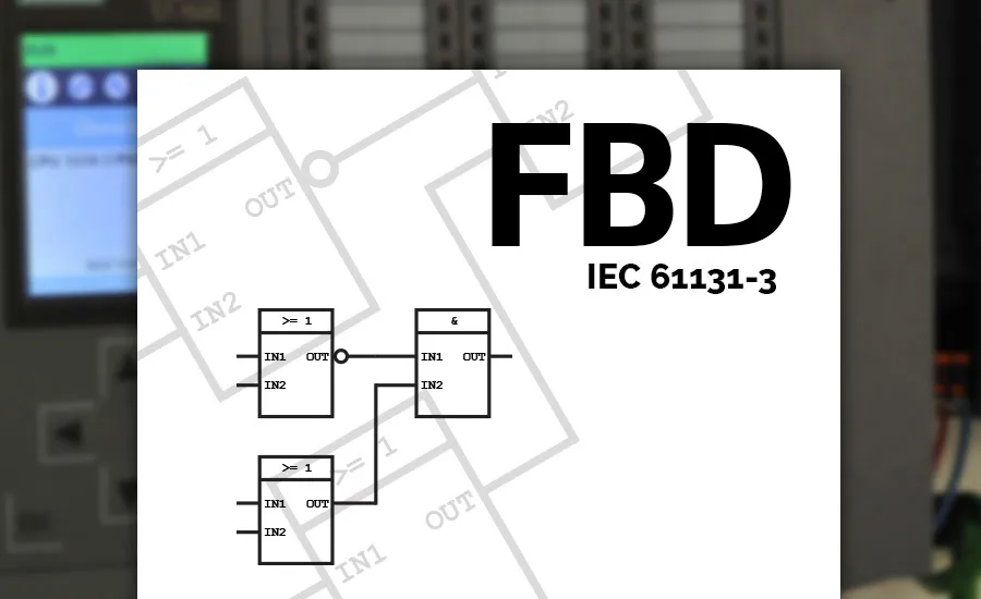
One of the official and widely used PLC programming languages is theFunction Block Diagram (FBD). It is a simple and graphical way to program any functions together in a PLC program. Function Block Diagram is easy to learn and provides a lot of possibilities.
As one of the official PLC programming languages described in IEC 61131-3, FBD is fundamental for all PLC programmers. It is a great way to implement everything from logic to timers, PID controllers, and even aSCADA systemin your solution, etc.
Most engineers love FBD because it is graphically a very common way to describe a system. Engineers like to put things in boxes. And that is exactly what the concept of function block diagrams is. FBD is very useful whenbatch control concepts from ISA-88are applied.
In this tutorial I will introduce you to some of the basic principles of FBD programming and the function blocks.
From systems engineering you might already know something also called function block diagrams. PLC function block diagram is not that different from it. What FBD offers is a way to put functions written with many lines of code into boxes.
Thereby we can easily connect them, to make a bigger PLC program.
As withladder logicandstructured text, function block diagrams or FBD is described in the standard IEC 61131-3 by PLCOpen. Most PLC programs are written with some amount of FBD. Because, even though you might write your functions in structured text. You still, most of the times, have to connect those functions.
Function Blocks
In FBD all functions are put into function blocks. They all have one or more inputs and outputs. The function of the block is the relation between the state of its inputs and outputs.
Here’s how a simple function block could look like:
Function block illustration in FBD
The function block is illustrated with a box. In the middle of the box is often a symbol or a text. This symbol represents the actual functionality of the function block.
Depending on the function there can be any number of inputs and outputs on the function block. You can connect the output of one function block to the input of another. Thereby creating aFunction Block Diagram.
Combining function blocks to make a basic function block diagram
There are many standard function blocks provided in FBD.But you can also make your own function blocks. Often, you will have to use the same piece of code in your PLC program multiple times. It could be a function for controlling a valve, a motor etc. With function blocks, you can make a function block specific for a motor and use it several times.
Let’s begin by having a look at some of the standard function blocks as described in the IEC standard for PLC programming languages. They provide a variety of functions from very basic to advanced.
Standard Function Blocks
In the standard from IEC, a lot of function blocks are described. Here’s an overview of the most important blocks in the official FBD description.
Bit Logic Function Blocks
The most basic functionality of a PLC program is logic. Combined calledcombinatorial logic. Logic is the simplest form of algorithm that, via the states of its inputs can set some outputs. Basically, there are two different bit logic functions or operations in FBD. With just these two you can derive a whole bunch of other logic functions.
But let’s start with the first one:
OR Logic Operation
At first I would like to introduce you to the OR function block. It takes 2 inputs and has 1 output, and works just like an OR gate.
If one of the inputs is true the output will also become true.
In FBD the block will typically look like this:
Function block representing the OR logic operation in FBD
As you probably have seen the symbol for an OR operation is>=1. It is basically the condition for the output. If the sum of the two inputs are greater than or equal to 1, the output becomes true.
Just like with all the other bit logic operations false is represented by a 0 and true by a 1. This can be illustrated with a truth table for the OR operation:
>=1
IN1
0
1
IN2
0
0
1
1
1
1
The functionality of the OR block is equivalent to a parallel connection of two contacts in ladder logic. If either one of the contacts are closed, the output is set.
When I say output here I mean the output of the function block. We can only connect the output pin to another function block. But what if we want to set an actual output or a bit with the block output?
This leads us to the next function block.
Assignment Operation
In most cases, you will connect the output of a function block to the input of another. But sometimes you will want to use that output to control one or more bits. This could for example be setting an output or a value for a variable.
To do this you need to use the assignment function block. And yes… This is a function block itself. Meaning that you cannot just set a memory address at the output of your block.
Assignment blocks work by assigning its input to a place in the PLC memory.
The function block also has an output you can use to connect to other function blocks. This is very useful because you can assign values anywhere in your function block diagram. Not just at the output of the last block.
The assignment function has the same functionality as a coil inladder logic.
Function block of an assignment operation in FBD
AND Logic Operation
The next function block I would like to introduce you too is the AND function block. Just like the OR-block this is one of the most fundamental function blocks in PLC programming.
It has two inputs and one output. It is very similar to the OR function but works a little different. Instead of one of the two inputs, this block requires both inputs to be a true set the output.
If both the inputs are true the output will also become true.
Function block representing the AND logic operation in FBD
This is how the truth table for AND block looks like:
&
IN1
0
1
IN2
0
0
0
1
0
1
If you know a bit of ladder logic, the AND function block is equivalent to a serial connection of two contacts in ladder logic. Both of them has to be true before the block evaluates its output to be true.
Negation Operation
Sometimes you will want to invert either the input or output of a block. To do that you have to use negation. It comes in different shapes, depending on the software you use.
In some cases it is a whole blocks itself. And sometimes it is just the small circle you can put on any pins of the function blocks.
NOT, invert RLO or negate assignment practically works by changing the signal to the opposite.
Negated function block/NOT function block
When a signal is inverted or negated it means that, if it is true it becomes false and vice versa. The small circle in the pin of the block represents exactly that function.
Not only is it the outputs that can be inverted. The inputs can also be inverted. Simply by putting the circle on the input pin. You’ll see later that inverting either all inputs or the output has the same effect on the function of a block.
Exclusive OR Operation
This block is a special case of the OR block. The input values on the OR block has to be greater than or equal to 1. But as you can see below, the Exclusive OR or just XOR block requires the two inputs to be equal to 1.
If for example both inputs are true, the output of the XOR will be false, since the sum of the inputs are greater than 1.
Exclusive OR function block XOR in FBD
Although it can be built with two AND and one OR function block, the XOR block is also provided as a function block itself in Siemens TIA Portal, Codesys and many more.
It is widely used to check if one and only one of two inputs are true.
NAND, NOR etc.
The next two function blocks are also build using the basic blocks. They arenegated blocks. It actually just means that the output of the block is negated.
Take for example the NAND block as illustrated below. As you can see, the NAND function block is really just the AND block with a negated output. NAND stands for NOT AND or Negated AND.
NAND function block from negated AND block
The truth table for this block is the exact opposite of the truth table for the AND block.
NAND
IN1
0
1
IN2
0
1
1
1
1
0
As mentioned before the functionality of the NAND function block can also be obtained by negating the inputs. Negating the inputs has the same effect as negating the output. Therefore a NAND block could also look like this:
NAND function made with negated inputs on AND block
Bistable Function Blocks
The next types of function blocks I will introduce you too are the bistable. I like to think of them as the simplest form of memory. You can either set or reset the output. The output (Q) remembers the last state of the set input (S1).
Give S1 a pulse, and Q1 will be set. Even though S1 then changes state to false, the output will still be true. You can say that Q1 remembers if anything happened at S1. That’s why I like to think of the bistable functions or flip-flops as memory.
Set/Reset
The function block is called SR or set/reset and this is how it looks like:
Set/reset function block (set dominant)
In order to get a better understanding how this function works, let’s look inside the function block. The function block body of the SR block shows that it is made up of 2 bit logic blocks. One AND function and one OR function.
The output of the AND function is connected to the input of the OR function. As one of the inputs on the AND function is Q1 which also acts the output for the whole block.
Many call this a flip-flop function. Q1 will remember that at some point S1 was true. This is until R or reset will be sat to true. Thereafter Q1 will be reset. The output (Q1) remembers and therefore I like to think of the block as a simple memory block.
Set/reset function block body
This type of block always has a priority. If both inputs are true what will happen?
SR-blocks has set priority. So in the case where both inputs are true, the output will be set.
But that’s not always what you want. And that will lead us to the next block.
Reset/Set
In some cases you might want to output to be reset when both inputs (S1 and R) are true. That is why we have to RS block.
It basically works in the same way as the SR block, but with reset as priority instead of set.
Reset/set function block (reset dominant)
Again, this block can be derived from two basic logic blocks. But since the SR/RS flip flops are so fundamental in PLC programming, they have their own function block.
Reset/set function block body
There are of course several ways to remember things. And although the flip flops are a very simple way to remember, the next types of blocks might be an even simpler form of memory.
Edge Detection
Detecting edges is very useful in both PLC programming and electronics. Of course I’m not talking about the edge of your kitchen table, but rather the edge of signals.
Let’s say you have an input with a push button connected to it. You want to be able to count how many times you press that button.
Normally you would just connect the input to a counter function block (more on those later). But if you remember the basic workings of a PLC you will know that the PLC has ascan time or a cycle time.
This time is usually very short (20-50 ms). When you press a push button (even though you press and release fast), the input will be on for way longer time (typically 100-200 ms). The input will be on for several scan cycles.
Each time the PLC reaches the counter block it will count one up since the input is true. For each time the push button is pressed the counter will count not only one up but 2, 3, 5 or even more.
To avoid this we are going to use edge detection blocks.
R_TRIG Function Block
The one edge we can look at in a digital signal is the rising edge. Sometimes also referred to as positive edge.
It happens when the signal goes from false (0) to true (1). In digital electronics when the voltage goes from 0 to 5V. The rising edge is what happens right when we push the button.
R_TRIG function block for detecting rising edge signals
When the input (CLK) detects a rising edge the output will be set. But only for a brief moment, since the rising edge happens so fast. Even though the input might be true for next scan cycles, the output will not be set more than one time. The output generates a pulse when a positive or rising edge is detected.
Here’s a diagram of the function block to make it easier to understand:
Function Diagram for R_TRIG Block
It takes a new rising edge to generate another pulse at the output. The block remembers, so to speak, if a positive edge was at the input. So in order to set the output again the input needs to go to false and then true again. Or as in our push button example; you need to release the button and press it again.
F_TRIG Function Block
Just like the rising edges you can of course also detect falling edges. When the signal goes from true (1) to false (0) is the falling edge.
F_TRIG function block for detecting falling edge signals
Sometimes the falling edge is also called negative edge. It also works by generating a pulse at the output but with a falling edge at the input.
Function Diagram for F_TRIG Block
A typical use for this block is to make something happen when another thing stops.
Let’s say you want a yellow lamp to be turned on when a motor stops. But you only want this to happen when the motor has already been started. So that the yellow lamp is only turned on the moment the motor stops.
Solution: Put and F_TRIG to detect a falling edge on the motor output. This can then generate a pulse to set the output for the yellow lamp.
Timer Function Blocks
With the previous blocks we wanted to make sure a signal was not longer than the scan time. But sometimes you will want to control the length of a signal, or when it happens.
This is where timer function blocks comes into the picture. Timers are some of the most used functions in PLC programming. They are divided into three different types of timers.
If you want to know more about timers and watch how they work in a PLC simulation you can read the article aboutPLC timers. You will find video tutorials on both theon delay timer,off delay timerandpulse timer.
Some argue that you will only need to use one of them, because with that you can derive all timer functions. But since all three are described in IEC 61131-3 and are provided in most software, I would like to introduce you to them all.
Pulse Timer (TP)
The first timer is called the pulse timer, because it is used to generate a pulse of a specific length.
It takes two inputs and has two outputs. So far, we have only seen function blocks where the inputs and outputs where boolean. This is still true for the IN and Q of the TP block. But it is a little different with the PT and ET. They both take variables of thedata type TIME.
PT stands for Preset Time and is an input to the block. This is where you put the time you want to pulse at Q to be. As soon as the input IN is true, the output Q will be set for PT time.
Timer Pulse (TP) Function Block
ET stands for Elapsed Time. This is the time Q has been active.
Say you want a ventilation fan to be on for 10 minutes. You will then have to enter 10m at the PT and set the ventilation fan to the output Q. In many cases it is then useful to see how long the fan has been running. That is what ET is used for.
Pulse Timer Diagram
You can see the functionality of the pulse timer a little more detailed in the time diagram above.
On Delay Timer (TON)
The next type of timer is the On Delay Timer or just referred to as TON. But instead of setting the time for the pulse, it is used to set a delay for the pulse.
When the input is on the timer will start counting. After the time PT has elapsed the output Q will be set. This is also the reason for its name.
It turnsonthe output after a delay
On-Delay Timer (TON) Function Block
The on delay timer has the same input and output pins as the pulse timer. And again, it still has the ET to see how much time has elapsed.
In the diagram for the on delay timer below the functionality is illustrated:
On Delay Timer Diagram
It is exactly this timer that some people claim is the only one you need. But before explaining why, let me introduce you to the third and last type of timer.
Off Delay Timer (TOF)
The functionality of the off delay timer (TOF) is very similar to the TON. But with one big difference.
It turnsoffthe output after a delay
In the moment the input is set to true, the output will be set. As long as the input stays true the output will stay on until the PT time has elapsed. After that time the output will be turned off.
Off-Delay Timer (TOF) Function Block
At first, this off delay timer may seem very similar to the pulse timer (PT). They also are, but with one crucial difference.
The output of the pulse timer will be on for PT time even though the input turns to false in the middle of the timing. This is because the timer looks for a rising edge at the input. With the off delay timer though the time will stop counting if the input comes back.
Off Delay Timer Diagram
These three timers are the official ones described in IEC 61131-3. Technically you can build all of them by using only the on-delay timer. This is done with a little bit of ladder logic.
Counter Function Blocks
The next type of function blocks have not only an input and an output more. They also take another data type. It’s time to look at thePLC counters.
Counting is very fundamental to PLC programming. How many products has the machine produced? In which step of the sequence is the tool? There are many reasons to use counters in a PLC program.
IEC provides three different standard counter blocks. One for counting up, one for counting down, and one for counting either up or down.
Let’s look at the first one, and start counting up!
Up Counter (CTU)
This counter block has three inputs and two outputs. Although this seems like a lot, they are all necessary to be able to count. But before looking at the details of each input and output, let me just briefly explain how the up counter block works.
Each pulse on CU will count CV up by 1. When CV >= PV then Q is set.
The input CU looks for a rising edge. When that happens the output CV is increased by 1. To be able to do that, the output CV needs to take another data type: integer.
As the integer is a 16-bit number (with the first one used for signed/unsigned) you can count up to 32767. Both the input PV and the output CV are of the data type integer. PV is the limit for when the boolean output Q is set.
Up Counter (CTU) Function Block
The reset (R) input is used to set the value CV to 0. We usually start counting up from 0 because, in that way, the output CV will always represent the number of pulses that occurred on CU.
For you that like textual coding languages here’s the function block body in structured text:
IF R THEN CV := 0; ELSIF CU AND (CV < PVmax) THEN CV := CV + 1; END_IF; Q := (CV >= PV);Down Counter (CTD)
It is not only a useful thing to count up. Sometimes you will also need to count down. Often you will want you PLC program to do an operation a certain amount of times. Here, the down counter comes in very handy.
Each pulse on CD will count CV down by 1. When CV <= 0 then Q is set.
It works exactly like the up counter, but instead of counting one up, it counts 1 down.This brings me to another difference between the up and down counter. Where to count from?
When counting up we usually just count from 0. But when counting up we need to set some value we can count down from. That is why we have to input LD. When LD is set to true the output CV is set to PV.
Down Counter (CTD) Function Block
The function block body looks like this in structured text:
IF LD THEN CV := PV; ELSIF CD AND (CV > PVmin) THEN CV := CV - 1; END_IF; Q := (CV <= 0);
Now that you’ve learned both how to count up and down it’s time to take a look at the last counter block.
Up Down Counters (CTUD)
It can sometimes be practical to be able to count both up and down. That is why the IEC also provides an official block for counting both up and down.
The counter has 5 inputs and 3 outputs. All of them has the same names as the inputs and outputs on the previous counter blocks. This block is a combination of the two previous blocks. All the inputs/outputs has the same function.
Up Down Counter CTUD Function Block
To really get to know how this function block works, let me show you the function block body:
IF R THEN CV := 0; ELSIF LD THEN CV := PV; ELSE IF NOT (CU AND CD) THEN IF CU AND (CV < PVmax) THEN CV := CV + 1; ELSIF CD AND (CV > PVmin) THEN CV := CV - 1; END_IF; END_IF; END_IF; QU := (CV >= PV); QD := (CV <= 0);
This code can look a bit complicated at first. But it really just is a combination of the up and the down counter. CU counts CV up by 1 and CD counts CV down by 1. Each of the outputs QU and QD are set with the same conditions as with the two previous counter blocks.
Comparison Function Blocks
I like to think of the next type of function blocks as asking questions. Is A equal to B? Is CV greater than PV? It is time to compare some numbers!
Comparing is actually something that already happened in many of the blocks we’ve already looked at. Take for example the OR block that compared two boolean inputs. If the total of them were equal to 1, the output would be set.
Now, it is not only boolean data types we can compare in FBD. In fact, we can compare all real numbers (sorry mathematicians, no imaginary yet) and most data types. This is not only handy, I will also promise you that it is something that you will use a lot.
Basic for all the comparison blocks is that they all have two or more inputs and one output. The inputs can take up any elementary data type and the output is boolean. You have to be careful when comparing data types, because it can be a bit tricky.
Let’s begin with the first basic comparator block:
Equality (=)
The equality function block is used to see if two variables are equal to each other. If so, the output will be set. I like to think of the block as asking this question:
Is IN1 equal to IN2?
Although this block might seem simple, you have to be a bit careful with what data types you compare here. Comparing integers with this block is probably the data type you will use the most. Let’s say you want an output to be set when the machine is in step 12. IN1 would then be the step variable and IN2 would be 12.
The three dots between the two inputs are there to illustrate that this block can take more than two inputs. For the output to be set, all of the inputs has to be equal. This function is described like this using structured text:
OUT := IN1 = IN2 = ... = INn
Equality Function Block
Comparing other data types with equality can cause some problems though. If you try to use equality to compare an analog value (real data type) to another real data type, you will see that it is very unlikely that they will ever equal each other.
For this block to set the output requires the two inputs to be exactly equal to each other. Remember that real data types are floating-point numbers. You may want something to happen when the temperature reaches 80 degrees. But if you use real numbers here the temperature has to equal 80.0 degrees exactly. For this type of comparison, it is better to use a combination of compare blocks. In that way, you can compare it to a range of numbers and not just one.
But when talking about integers and sometimes also words, the equality block is very useful.
Inequality (<>)
But what if you want to check if some numbers aren’t equal to each other? Of course you could just negate the output of the equality block. But that would be rather confusing. And why do that when there’s a block for doing exactly that.
The block works in the same way as the previous but checking for inequality instead of equality. The question to remember the functionality of this block could be:
Is IN1 NOT equal to IN2?
If so, the output will be set. But only as long as they are not equal. As soon as the inputs are equal the output will be turned off.
Inequality Function Block
To you who are already familiar with structured text you will know the symbol for inequality. It is similar to what in many programming languages is noted like this:!=. But in PLC programming inequality is noted this way<>.
Be aware that this block only takes two inputs.
Less Than (<)
If you remember before we had a problem with comparing real data types with equality. This and the next block might be the solution to that. Because with this block we can check if a variable is within a range of numbers.
Officially this block is calledincreasing sequence. But less than is a way more simple name to remember it by. Think of it as asking this question:
Is IN1 less than IN2?
It is basically checking if the value of the first input is less (smaller) than the value of the second input. The block works very well with real numbers since you can easily check if e.g. a temperature is less than 80.5 degrees.
Less Than (Increasing Sequence) Function Block
There’s a reason the official name for this block is increasing sequence. Just like the equality block you can extend this block with more than two inputs. When doing that the official name makes a whole lot more sense.
Because with multiple inputs the values of those has to make up an increasing sequence of values. In1 has to be less than IN2, that has to be less than IN3 and so on. The function can be described textually like this:
OUT := (IN1 < IN2) AND (IN2 < IN3) AND ... (INn-1 < INn)Greater Than (>)
When you can make an increasing sequence you can of course also make a decreasing sequence. Or put in more simple words. You can also check if some value is greater than another value. The question this block asks is this:
Is IN1 greater than IN2?
But just like the previous block, this block can also take more than two inputs. That’s why this block also has to take a sequence of numbers, but this time adecreasing sequencein order to set the output.
Greater Than (Decreasing Sequence) Function Block
Each text input has to be smaller than the previous, thereby creating a decreasing sequence. Written in a textual language like structured text, the function of the greater than block looks like this:
OUT := (IN1 > IN2) AND (IN2 > IN3) AND ... (INn-1 > INn)
The combination of the greater than and less than blocks can also be very useful. When talking analog values you will often want to check if they are within a certain range. E.g. if a temperature is between 90 and 100 degrees. Here you could check if the temperature is greater than 90, and thereafter check if it is less than 100.
Combining the comparison blocks is widely used. You will often see the equality block combined with either less than or greater than. Although these are just a combination of blocks they often have their own function blocks:
Less than OR equal to
Greater than OR equal to
Selection Function Blocks
Comparing two or more values is useful. But sometimes, instead of comparing, you will have to choose between values. The selection function blocks give you that opportunity.
What they all have in common is that they give you the option of selecting a value. With or without conditions. The essence of these blocks is really just an assignment. You will select one of the inputs and assign it to the output of these blocks.
Move
The first and most simple selection block is the move function block. In fact, you have already seen this block before. Or at least a block with the same functionality. The assignment function block.
What this block does is that it assigns the input value to its output. And guess what. This block does exactly the same thing. You might wonder why FBD provides two blocks with the same function. They are also similar, but with one crucial difference.
While this block can be used with any data types, the assignment block can only be used with boolean data types. With the move block you can move any data type to any data type.
For you that like structured text, the representation of the block looks as simple as this:
OUT := IN
Provided in function block diagram the moving block looks like this:
Move Function Block
As you can see this block only has one input and one output. The concept of selection doesn’t really apply to this block, since you only have one value to select. Many times though you will be able to add more outputs to the move block. A moving block can thereby be used to move a value to different places.
When I said this block works with any data type, I really meant it. You can move values from any data type to any data type. You don’t even have to put the same data type in the output as the input. You’re free to move e.g. an integer to a real, a TIME to a double word and so on.
This makes the moving block a bit tricky. You have to be really careful when moving from one data type to another. For beginners, I highly recommend that you only move values to the same data type as the input. As a matter of fact, I would rarely recommend mixing data types even for professionals. It just makes your PLC program complicated.
Binary Selection (SEL)
Binary selection drags us a little closer to the concept of selection. It gives you the opportunity to select between two values to then assign to an output.
The name indicates that you with a binary (boolean) input can select one of two input values. Therefore this block has three inputs. One condition (G) and two values (IN0, IN1). The condition takes a boolean data type and is used to select between the two values.
Binary Selection (SEL) Function Block
You will most likely have noticed that the input names are a bit different than with the other function blocks. That is only to make the block easier to understand. Since the condition (G) can take two different values 0 and 1, it makes sense to call the inputs IN0 and IN1.
If G is 0 the input IN0 will be selected. And if G is 1 the input IN1 will be selected. The value of the selected input will then be assigned to the output (OUT).
Again, this functionality can be represented in structured text:
IF G = 0 THEN OUT := IN0 ELSIF G = 1 THEN OUT := IN1 END_IF;Extensible Multiplexer
In some cases, you may even have more than two values you want to select from. This is where the extensible multiplexer comes into the picture. You might even find the word multiplexer familiar if you know a few digital electronics. And this block has the same functionality – to choose one out of many inputs.
Like the previous block, this block has two types of inputs. A condition (selector) and some input values. The block selects one of N inputs depending on the value of the selector.
Extensible Multiplexer (MUX) Function Block
Unlike the binary selector the condition input, named K in this block, can not only take a boolean data type. In fact, it can take up any elementary data type. Although the only data type that really makes sense to use here is an integer.
As you have to choose between inputs from IN0 to INn it only makes sense to give the condition K a whole number. Actually it is only valid to give K a number between 0 and n. The concept of the function may look like this:
OUT := INK
Where K has to be within the range 0 – n, where n is the number of inputs.
Extensible Minimum Function (MIN)
So far you have seen how to select values using a condition input. That input could be either binary or an integer depending on how many inputs you have to choose between But sometimes you will want to select a value depending on the values themself. It could be that you want to select the highest or the lowest value among different variables. With the next two function blocks, you can do exactly that.
Extensible Minimum (MIN) Function Block
Choosing the variable with the smallest value is something that I can guarantee, that you will use at some point. The official name for this function block is extensible minimum, but often just called minimum or MIN. It is called extensible because you can add any number of inputs on the block. All the inputs can take any elementary data type, and they can even be of different data types on the same block.
OUT := MIN (IN1, IN2)
What will be assigned to the output of the block is always the value of the smallest input. Or put in other words – the input with the minimum value will be selected.
Extensible Maximum Function (MAX)
When you have a block for finding the minimum value, you will of course also have a block for finding the maximum value. FBD also provides a standard function block for doing that. It works exactly the same way as the minimum function, but selects the variable with the maximum value and assigns that value to its output. Also this block takes any elementary data type as input and output.
Extensible Maximum (MAX) Function Block
With both these blocks, you should be aware which data type you use at the output. If you are trying to find the maximum value of two real data types e.g. 80.46 and 206.95 and you use integer as output, the output will simply be 206.
OUT := MAX (IN1, IN2)
A smart feature with these two blocks is that you can also compare time and date data types. Say you have a lot of date stamps in your PLC program and you want to find the latest. With the maximum function, you can always find the most recent date.
Limiter (LIMIT)
By combining the two previous function blocks we can create a whole new function. This function is not so much about selection, but rather about limitation. That is why this function block is called a limiter. More than often you will want to set limits to a range of values in a PLC program.
Limiter (LIMIT) Function Block
The limiter function is really just made up by the minimum and maximum functions. This can be seen if we take a look at the function block body:
OUT := MIN ( MAX (IN, MN), MX)
What really happens here is that you set a minimum and a maximum limit for whatever variable you put at the input (IN). The min and max values are set at the inputs (MIN and MAX) and all three inputs can take any elementary data type.
Make your own function blocks
All these function blocks above are most of the ones described in the IEC 61131-3, the official standard for PLC programming languages. There are many more function blocks provided in the function block diagram. Actually there is almost a function block for every operation you can do in PLC programming. Among those are:
Arithmetic Function Blocks
Bit Shift Function Blocks
Character String Function Blocks
Conversion Function Blocks
Communication Function Blocks
And many more…
I highly recommend that you just start out by playing around in your Automation IDE like TIA Portal or Codesys. Try creating simple PLC programs using function block diagram programming. I find that is the best way to learn about new function blocks.
The point here is that every function block represents a function. Inside the function block body, you will find that the function is described in either structured text, ladder logic, or another PLC programming language. There are many standard blocks providing you with a lot of different functions. But sometimes it’s just not enough.
This is why you will need to build your own function blocks. This is in fact one of the cornerstones in structured PLC programming. Stay tuned on PLC Academy to learn more about that
AWA (Aluminium Wire Armour) A type of cable armouring for mechanical protection, used for 3 phase cables.
CPE (Chlorinated Polyethylene) An oil, ozone and heat resistant thermoplasticsheathing material.
CSP / CSPE (Chlorosulphanated Polyethylene) An oil, ozone and heat resistant elastomeric compound used as bedding and outer sheath material. DuPont manufacture this material underthe registered trade name "Hypalon".
Dekoron® Registered trade name for a range of instrumentation cables insulated and sheathed with a flame retardant PVC. The standard range includes up to 50 pairs and up to 36 triples in either 0.5mm2 or 1.5mm2 conductors. Larger conductors may be specified, as can options of Lead Sheathing, SWA, or HF insulation and sheath materials.
DWA (Double Wire Armour) Two layers of wire armour. Typically used insubsea cablesand wrapped contra-helically for bottom stability.
EPR (Ethylene Propylene Rubber) A water and ozone resistant, flexible, cross linked high gradeinsulation materialand sometimes as asheathing material.
FR (Fire Resistant / Flame Retardant) Fire Resistant - the property of cables to continue to function while under the influence of fire. Cables that are Fire Resistant tend to provide circuit integrity even when burned and maintains integrity after the fire has extinguished. In most cases, the cables will withstand a water spray and still provide circuit integrity.
Flame Retardant - the property of cables to retard or slow the progress of fire and flame along the cable.
This is achieved through the use of materials that do not readily burn and will tend to self-extinguish.
GSWB (Galvanised Steel Wire Braid) A type of cable armouring for mechanical protection.
HDPE (High Density Polyethylene) Generally used as a subsea cablesheathing materialwhere it provides high resistance to water penetration, is very hard, has low coefficient of friction, and is abrasion resistant.
HF (Halogen Free) Halogenated plastics (ie. those that contain chlorine, fluorine, bromine, iodine and astatine) when ignited will tend to release toxic and corrosive gases, which has potential safety implications, eg. obstruction of escape routes. Halogen free plastics, as the name suggests, do not contain halogens.
HOFR (Heat, Oil and Flame Retardant) Refer to FR (flame retardant).
LAS (Lead Armour Sheath) Used for chemical protection against petrochemicals and other chemicals, that can weaken the insulation materials used.
The lead sheath sits under the mechanical protection (e.g. SWA), to ensure the chemical barrier isn't compromised.
LSF (Low Smoke and Fumes) Low smoke and fume emissions when the cable is on fire. Note that it may still contain halogens.
LSTA (Low Smoke, Toxicity and Acidity) Uncommonly used term for bedding and sheathing materials with low smoke, toxicity and acidity properties. Halogen free materials such as SHF2 are more or less equivalent to LSTA materials.
LSZH / LS0H (Low Smoke, Zero Halogen) Refer to HF (halogen free). MGT (Mica Glass Tape) A fire resistant tape usually wrapped around the insulated conductor bundle beneath the innear sheath.
MICC (MI, MIMS) Mineral-insulated copper-clad cable is a variety of electrical cable made from copper conductors inside a copper sheath, insulated by inorganic magnesium oxide powder. The name is often abbreviated to MICC or MI cable, and colloquially known as pyro (because the original manufacturer and vendor for this product in the UK is a company called Pyrotenax). A similar product sheathed with metals other than copper is called mineral insulated metal sheathed (MIMS) cable.
Neoprene® Refer to PCP (polychroloprene)
NYL (Nylon sheath) A nylon sheath (or sometimes described as a sock) is typically used for termite protection in underground cables and also as a sheathing material.
PCP (Polychloroprene) This is an oil resistant, toughsheathing material, that is used mainly in mining cables as an outer sheath. DuPont registered trade name for this product is "Neoprene".
SCN (Screen) A tape or braid, usually metallic (copper, aluminium) or semi-metallic (PETP/Al), wrapped around the cable cores to keep out or contain unwanted radiation / interference.
SHF2 Halogen free elastomeric compound commonly used for inner sheath / bedding and outersheathing materials.
SWA(Steel Wire Armour) A type of cable armouring for mechanical protection.
TAC (Tinned Annealed Copper) Annealed copper conductors with surface tinning for rust prevention. Annealing refers to the process of gradually heating and cooling the copper making it more malleable and less brittle.
TCWB (Tinned Copper Wire Braid) Typically used for flexible cable armouring of instrument cables.
TPE (Thermoplastic Elastomer) A plastic material compounded so it displays characteristics like an elastomer. TPE is normally tough, cut resistant, flexible, smooth, with vibrant colouring.
XLPE(Cross-Linked Polyethylene) High gradeinsulation materialof cross-linked polyethylene chains giving good high temperature performance.
□ 과전류보호장치 선정방식의 국제표준화(KEC 212) ㅇ 기계기구 정격전류에 종속된 과부하보호장치 정격 선정방식 탈피 ㅇ 과부하보호와 단락보호를 포함한 과전류보호방식의 명확화 - 과부하보호 : 전선의 과부하 보호점(1.45 Iz)에 근거한 보호장치 정격전류(In) 선정 및 기동전류 등을 고려한 규약동작전류 특성 검토
- 단락보호 : 단기 허용온도 도달시간, 전동기 돌입전류, 회로 최대고장전류 등 단락보호 장치 선정 근거 제시 ㅇ 보호장치의 분기점 설치 원칙 및 예외 설치를 위한 보완조치 명확화 - 분기점 : 배선의 변경 등으로 인해 허용전류가 작아지는 지점 - 상위 보호장치에서 하위 분기회로 보호 시 보호범위까지 거리 제한 없음
구분
현행 배선 선정방식
KEC 배선 선정방식
과전류 보호장치 정격전류
[과부하보호] •전등・전열회로: Iz 이하 •코드, 전등기구용심선 등 전로: 15A 또는 20A •정격 50A 초과 기계기구 전로: 기계기구 정격의 1.3배 이하 •전동기 등만의 전로: 2.5 Iz 이하
[단락보호] (정격 선정 관련 별도규정 없음)
[과부하보호] •정격전류 선정 시 고려사항 - 부하의 설계전류 - 전선의 과부하 보호점 - 전동기 기동전류 [단락보호] •단락보호장치 선정 시 고려사항 - 전선 허용온도 도달시간 [단시간사고,
등] - 전동기 돌입전류 유형 - 회로의 최대고장전류
과전류 보호장치 설치위치 (분기점기준)
•3m 이내 : 설치 원칙 •8m 이내 : Iz2 ≥ 0.35 InP1 •제한없음 : Iz2 ≥ 0.55 InP1
•분 기 점 : 설치 원칙 •3m 이내 : 감전・화재보호 전제 •제한없음 : P1로 P2 전단 단락보호
* IzN : 도체 N의 허용전류, InPN : 보호장치(PN)의 정격전류
□ [필독] 주의사항
ㅇ 상기 내용은 현행 「판단기준」 대비 변경된 일부 규정에 대한 요약자료로서 상세사항은 「KEC」 해당 규정 및 전체 규정, 발간된 기술지침서, 관련 교육 등을 통한 구체적 확인 필요
ㅇ 기술(참고)자료
- [KEC 제.개정확인] 기술기준홈페이지(kec.kea.kr) => 커뮤니티=>공지사항
- [배선분야 지침서] 배선설비의 설계 및 공사방법에 관한 기술지침
- [접지분야 지침서] 접지시스템 설계방법에 관한 기술지침 - [보호분야 지침서] 감전 및 과전류보호 설계방법에 관한 기술지침
□ 종별 접지설계 방식 폐지(KEC 140) ㅇ 접지대상에 따라 일괄 적용한 종별접지(1종, 2종, 3종, 특3종) 폐지(’21 시행) ㅇ 국제표준의 접지설계 방식 도입을 통한 현장 특화된 접지시스템 구분 설정
- 계통접지 : 전력계통의 이상현상에 대비하여 대지와 계통을 접속 - 보호접지 : 감전보호를 목적으로 기기의 한 점 이상을 접지 - 피뢰시스템접지 : 뇌격전류를 안전하게 대지로 방류하기 위한 접지 ㅇ 접지설계 방식의 국내 수용성 향상을 위한 접지시스템의 시설 종류 설정 - 단독접지 : (특)고압 계통의 접지극과 저압 접지계통의 접지극을 독립적으로 시설하는 접지 방식 - 공통/통합접지 : 공통접지는 (특)고압 접지계통과 저압 접지계통을 등전위 형성을 위해 공통으로 접지하는 방식, 통합접지 방식은 계통접지・통신접지・피뢰접지의 접지극을 통합하여 접지하는 방식 ㅇ 수전전압별 접지설계 시 고려사항 - 저압수전 수용가 접지설계 : 주상변압기를 통해 저압전원을 공급 받는 수용가의 경우 지락전류 계산과 자동 차단조건 등을 고려하여 접지설계 - (특)고압수전 수용가 접지설계 : (특)고압으로 수전 받는 수용가의 경우 접촉·보폭전압 과 대지전위상승(EPR), 허용 접촉전압 등을 고려하여 접지설계
접지대상
현행 접지방식
KEC 접지방식
(특)고압설비
1종: 접지저항 10Ω
•계통접지 : TN, TT, IT 계통 •보호접지 : 등전위본딩 등 •피뢰시스템접지
600V이하설비
특3종: 접지저항 10Ω
400V이하설비
3종: 접지저항 100Ω
변압기
2종: (계산요함)
“변압기 중성점 접지”로 명칭 변경
접지대상
현행 접지도체 최소단면적
KEC 접지/보호도체 최소단면적
(특)고압설비
1종: 6.0 ㎟ 이상
상도체 단면적 S(㎟)에 따라 선정* • S 16 : S • 16≺ S 35 : 16 • 35≺ S : S/2 또는 차단시간 5초 이하의 경우 •
600V이하설비
특3종: 2.5 ㎟ 이상
400V이하설비
3종: 2.5 ㎟ 이상
변압기
2종: 16.0 ㎟ 이상
* 접지도체와 상도체의 재질이 같은 경우로서, 다른 경우에는 재질 보정계수(k1/k2)를 곱함